Category Orlogsværftet O-Maskinen
O-Maskinen – Related posts
O-Maskinen – Introduction
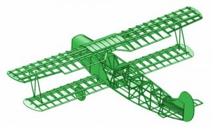
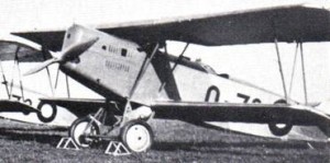 O-Maskinen is going to fly again, after 70 years.
This time as a model.
I have finally managed to track down some 3-views of this plane. I will document the design and construction of this scale model on this thread.
The O-maskine was a Danish trainer designed in 1926. For more information regarding this plane, see the O-Maskine details page. There are also some photos of the O-Maskine in the gallery.
Research
This plane had a wing-span of 10.66m, length of 8.4m and a height of 2.7m. Note that the span of 10.66m MIGHT be a typo in my source material. It MIGHT be 10.6m. If the 3-view is to scale, this discrepancy will show up when I start the design. (IT IS A TYPO – 10.66m tally with the 3-view. The correct wing-span is 10.6m). As always, my models are in scale 1:5, giving this model a wingspan of: 2.120m, length of 1.68m and a height of 0.54m.
The first thing I do is to get out the 3-views and study them in detail. In the case of the O-maskine 3-view, there are a few structural details that I am unsure about, i.e. are the horizontal lines merely canvas stitching or are there some structural steel-tubing or wood longerons underneat? I also need to determine those details that varied from plane to plane – in this case the oil-cooler, the shape of the horizontal elevator and the cockpit areas.
Horizontal Lines
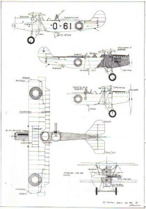 From photos it’s obvious that the horizontal lines are structural. There are two longerons on each side of the fuselage. However, these are surely wooden, as they are not shown on the drawings of the fuselage metal frame. Most likely they are simply there for cosmetic and aero-dynamic reasons – to prevent vertical steel tubing and the bracing wires from showing through the canvas.
Details
Two different oil coolers were used on the original aircraft, one square and one rounded. On a model like this, they are not part of the fuselage as such, and more an ‘add-on’ detail, so I do not need to worry about it at this time. The remaining major detail is the shape of the horizontal elevators. They were either rounded or square. I will design both.
O-Maskinen – Construction Method
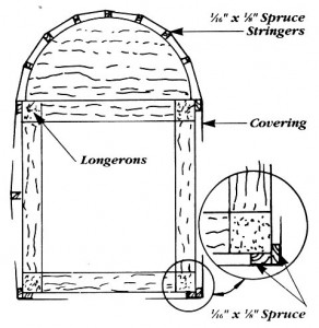 The original plane was canvas covered, and I will duplicate this using solartex.
The O-maskine was painted white/grey. Sun would not prenetrate the covering, so I don’t have to duplicate every single internal detail. I must, however, make sure that from the outside, it looks authentic. I will use the method shown on the attached drawing.
The wings were fabric covered, and I will use a standard build-up wing. There are some details, such as strut-attachment points and handles at the wing-tips. These are not too difficult to simulate. The front of the fuselage was alu-clad. I build up this area balsa sheeting or possibly lite-ply.
O-Maskinen – A few words on CAD
Now that I have decided on the construction method, I will start the actual drawing. I’m using a program called Alibre. It is very similar to Solidworks in the way parts are entered. It doesn’t look as ‘polished’ as Solidworks, but the cost is unbeatable. They had an offer when I bought it; $99. Normal price $999. For reference, Solidworks is about $5000.
First thing is to import the 3-views. During import, I scale the drawings so that they are in 1:5 size of the original plane. I make all my planes in scale 1:5, which means 1 cm on the drawing corresponds to 1 cm on the model. I know some people use the scale of the original plane when they draw. That would make sense if you had access to the actual factory drawings, but I don’t.
Besides, I have a library of standard R/C components like engines, R/C receivers and servos, making it much easier to handle, when I draw it at 1:5 scale. There are many ways to skin a cat, and no hard and fast rules, so do what you are comfortable with. With CAD you can easily scale things up and down, so no big problem
| Scale Dimensions | I O | II O |
|---|---|---|
| Wing span | 2120 mm | 2120 mm |
| Length | 1680 mm | 1680 mm |
| Height | 540 mm | 540 mm |
OK, so now that the 3-views are imported, I can use them to take measurements off of. It’s also possible to trace parts and formers directly from the plans.
I know some people use the CAD software to loft the entire plane and then slice it up into formers and what have you, but I haven’t had much luck with that method. Alibre’s lofting function is just not that powerful. In any case, I prefer to draw the plane, part by part, and then use Alibre to put it them all together.
Anyways, the import is now done, and I’m ready to draw.
The O-Maskine is my first “stick and fabric” type plane, so the construction method will be a bit different from the other planes that were planked and covered with fibre-glass. I really look forward to this build. I think it will be rather easier – particularly the wing/fuselage attachments.
Let’s GO!
O-Maskinen – Wing Construction
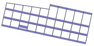 The O-Maskine wing-construction was fairly standard for a plane of that era. However, the wing spar had the leading edge covered in plywood – like the Fokker D.VII. This allowed for an almost perfrect cantilever design. The wings had very thin struts but, of course, no flying wires. The O-Maskine had the petrol tank mounted in the top wing, making the wing center thicker than the wing-tips.
The only real unknown is the actual wing-profile used. I will be using the airfoil shown in the 3-view. Although it may not be entirely correct, it is the one that best matches the available photos.
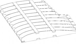 The front view of the 3-view shows that the center section with the fuel tank has a fixed wing thickness, and the wings themselves were tapered towards the wing-tips.
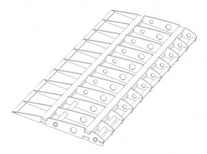
The actual construction of the wing is done by drawing the outline of the wing profile at each end of the wing, and then lofting the wing. After that, the wing is “sliced” into 3mm thick wing ribs at the proper locations. Finally, cut-outs for spars etc. are added to the ribs. The cut-outs are done so that the different pieces interlock, making alignment easy during construction.
The next step is to insert hard-points for the mounting of the wings, the wing-struts, servos and aileron hinges.
O-Maskinen – Fuel-Tank
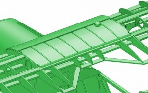
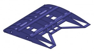 The fuel-tank is giving me a lot of headaches. It’s situated in the center-section of the top wing. The trailing edge of the top wing has a notch in it for easier access for the pilot. I have no idea how the wing profiles looked like between the fuel-tank and the trailing edge.
I have a photo showing the internal structure of the wing, but it’s really not too clear. However, it suggests a concave shape, as shown on my drawing. However, it goes against everything I have ever seen before. In any case, I am not happy with this part. I will have to revisit it again later.
The center section will be 100% sheeted.
O-Maskinen – Wingtips
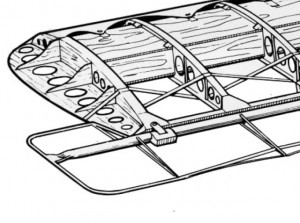 Before the servo installation and the wing-mounting, I will quickly draw the wing tips.
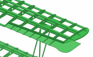
The 3-view is not very clear in this area. However, photos of the Fokker Dr 1 show EXACTLY the same wing tip as the O-Maskine. We can therfore assume that these two machines use the same internal structure. Obviously the Fokker wing shown in the pencil sketch differs from the O-Maskine in the spar and leading edge plywood construction, but the wing-tip must be the same.
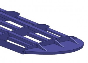 It’s very difficult to cover this type of wing-tip with canvas, particularly at the trailing edge. The sketch of the Fokker triplane also shows how Fokker fixed this problem.
Obviously we only care about the external shape of the wing-tip, so we don’t need exactly the same structure. Here is what I have come up with.
O-Maskinen – Lower wing
O-Maskinen – Wing Center Section
I have finally managed to get a decent photo of the O-maskinen center wing section and fuel tank. I will have to update the model slightly, as the cut-out for the pilot is fairly flat and not quite as curved as I had expected.
O-Maskinen – Fuselage
O-Maskinen – New Photos
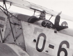 I have now received several photos of this aircraft. The cut-out for the pilot in the upper wing can now be rectified. The pictures also show various other details, such as metal brackets, wheels, fabric stitching, instrument panels etc., that needs to be incorporated into the model, before it is completed.
O-Maskinen – Minor Fixes
I have corrected the center section of the upper wing. It was simple enough. Just modify the shape of the center formers from convex to concave.
The other things that I have completed are the rudder and the landing gear. The landing gear is made from piano wire and attached to the fuselage via a hardwood mount. The gear on the real aircraft looked rather flimsy, and I have to emulate that. The wire will be silver soldered and then have balsa fairings glued to the outside to give the wires a teardrop cross-section.
The rudder was of standard construction (welded steel) and I am going to use laminated balsa for that.
O-Maskinen – Ailerons, finally
O-Maskinen – Photos (sort of)
I have just returned from Spain, where they have a Fokker C.III, which is the successor to the Fokker C.I that the O-Maskinen was based on. The wings, fuselage and empenage looks really similar, while the the engine, cowl, and engine cooler were much improved on the O-Maskinen. I will go through the Fokker C.III photos and see what the differences are, and what bits are identical, and can be used as the basis for the O-Maskinen model.
O-Maskinen – Engine Mounting Box
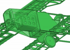 The engine mounting box was quickly made. It is made from 6 mm plywood and continues through the firewall. The lower wings are also mounted to this structure, hopefully resulting in a really strong design.
The engine box is big enough to contain the fuel tank and the throttle servo, but small enough that the elevator and rudder servos can fit below it.
O-Maskinen – Wingtip Problems
After looking at the Fokker, and my model, it is clear that the wingtips needs to be redone.
Furthermore, I have found some photos of the internal structure of the ailerons, and they show a different aileron shape than on the 3-view, so the ailerons have to be redone as well.
O-Maskinen – Book (Sort of)
O-Maskinen – Connections
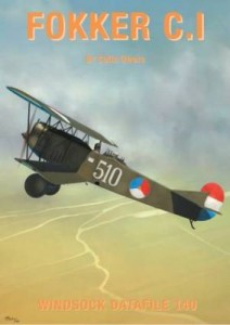
The C.I booklet arrived today, and it is (as usual for Windsock) full of photos. It also talked briefly about the O-Maskinen, and the C.III in Spain. I now know how they interrelate in much detail. My biggest surprise is that the C.III is practically identical to the C.I, with the exception of dual controls and a Hispano-Suisa engine. So, I CAN use the photos of the C.III I took in Spain for the detailing work.
Great stuff!
O-Maskinen – Status
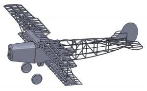
It is time to complete this design. I only need to do the following:
- Ailerons and new wingtips.
- Landing gear.
- New rudder.
- New elevator.
- Struts.
- Gun mount and gun ring.
- Instrument Panel.
- Fuel Pipes and gauges.
- Install R/C equipment.



 05/04/2015



Leave a reply