I found a model of this ugly aircraft at Teknisk Museum in Helsingør the other day. Note that the pilot was sitting in an open cockpit on top of the passenger cabin.


 06/11/2011
 Farman Jabiru
I found a model of this ugly aircraft at Teknisk Museum in Helsingør the other day. Note that the pilot was sitting in an open cockpit on top of the passenger cabin.
18/09/2012
Farman Jabiru
This should be a fun airplane to design. The fuselage is very simple, and so are the wings and the empenage. Only problem, really, is the engine pods. I will start on this airplane real soon.
Scale: 1:10
Length: 1.392 m
Wing span: 1.90 m
05/04/2015
Farman Jabiru
03/06/2011
Fokker F.III Gruhlich
 Coming soon…
05/04/2015
Uncategorized
03/06/2011
Fokker F.VIIa
 The Fokker F.VIIIa was designed by the Dutch aircraft designer Anthony Fokker during 1925. It was the world’s first passenger plane with 3 engines. The F.VII could carry 8-12 passengers, and was the choice of many European and American airlines, including DDL, the Danish Airlines, which is the aircraft I will be modelling here.
Specifications:
Crew: 2
Capacity: 8-12 passengers
Length: 14.60 m
Wingspan: 21.70 m
Height: 3.90 m
Empty weight: 3050 kg
Loaded weight: 5200 kg
Powerplant: 3 × Wright J-5 Whirlwind radial engines, 220 hp each.
Cruise speed: 170 km/h
08/09/2012
Fokker F.VIIa
 I’ve found this Russian plastic kit of a Fokker F.VIIB/3m which I will be using as reference.
08/09/2012
Fokker F.VIIa
Coming soon…
05/04/2015
Fokker F.VIIa
05/04/2015
Friederichshaven F.F.-49
04/09/2011
Friederichshaven F.F.-49
Coming Soon….
05/04/2015
General Dynamics F-16
20/06/2012
General Dynamics F-16
 After a great, but wet, Royal Danish Airforce centenial airshow in Aalborg last weekend, I have become really really really interested in the F-16. Loads of display teams, including the Danish, Belgian and the Dutch, showed off the capabilities of this magnificent aircraft, and it was amazing. This will be my first jet model. My second will probably be the Sukhoi Su-27 or the MiG-29.
27/08/2011
Orlogsværftet-H-maskinen
 H-Maskinen is going to fly again, after almost 90 years.
This time as a model.
H-maskinen was an aircraft designed and build by Orlogsværftet (Naval Dockyards) in Copenhagen. The first flight was in 1917 and was in service from 1917 to 1924. A total of 9 were built.
Very little is known about the aircraft, and only a handful of photos exist. However, after a lot of research at the national archives, other museums, and with help from private individuals, I have managed to acquire enough information to build a 1:5 scale model.
For more information about this aircraft, look here.
27/08/2011
Orlogsværftet-H-maskinen
 As noted earlier, I have a fairly complete set of plans for the full-scale aircraft, which I will be using for this build.
27/08/2011
Orlogsværftet-H-maskinen
This plane had a wing-span of 11.54 m, length of 8.0 m and a height of 3.15 m. As always, my models are to scale 1:5, giving this model a wingspan of: 2.308 m, length of 1.60 m and a height of 0.63 m – a fairly nice sized model.
This aircraft is a bit unusual, in that I have the construction drawings, and instead of trying to add more details to a 3-view based on photos, I now have to do it in reverse, i.e. I have way too many details and need to reduce the complexity of the model. So, in this case, there is absolutely no guesswork.
27/08/2011
Orlogsværftet-H-maskinen
This aircraft is pretty simple to build. I will enter all the blue-prints into the PC and make a 3D-model of them, trying to figure out how all the different parts fit together. Since the actual assembly drawings are missing, it might be a bit of a challenge. However, I hope I can figure it out.
27/08/2011
Orlogsværftet-H-maskinen
The fuselage of the H-Maskinen was of standard design for an aircraft of that period, and consisted of wood and canvas. Metal brackets were used to hold it all together, and turn-buckles and piano wire were used to true it up.
The canvas would have been silver-doped, like all the other Royal Danish Army aircraft of its day, and thus slightly see-through. I therefore have to design the model in that fashion too. If the canvas had been painted, and not see-through, it would have been much easier to make the model.
Anyway, I have first drawn the fuselage in Alibre CAD. It is not very detailed this time, as I do not imagine that I will be selling any of these plans. They are after all only relevant for a handful of Danish large-scale enthusiasts.

I then printed out the side-view on a sheet of paper, and glued all the spruce stringers together based on the drawing.

Next, I added the internal stiffeners in the cockpit area, exactly where the real aircraft had been reinforced. I then added some 0.8mm plywood where the actual aircraft had plywood sheeting.
Since the H-Maskinen had an open cockpit, it is possible to see its inside it, and it must be decked out with all the right details, including the internal reinforcements.

I then built the other fuselage side on top of the first one, to make sure they came out 100% identical. A piece of plastic sheet was placed between the left and right sides, to prevent the two sides getting stuck together.
18/09/2011
Orlogsværftet-H-maskinen
The next step will be to join the two fuselage sides and add some top and bottom formers.

Here is what the CAD looks like.
05/04/2015
Orlogsværftet-H-maskinen
09/09/2012
Heinkel He-59
 This aircraft first caught my attention when I was visiting the local museum. Aalborg used to have three airports during the war, and this aircraft was used as an ambulance plane at Aalborg See.
The Heinkel He-59 was build just after WWI, and was considered obsolete at the start of WWII. However, it proved to be very versatile and was used for mining, ground attach, rescue, transport, electronic warfare and spy-missions.
Specifications:
Wing span: 23.70 m (77 ft. 9.5 in.)
Length: 17.40 m (57 ft. 1.75 in.)
Height: 7.10 m (23 ft. 3.75in.)
Empty Weight: 6,215 kg (13,702 lbs.)
Max Weight: 9,000 kg (19,842 lbs.)
Engines: 2 x BMW IV, 660 hp each.
Maximum Speed: 215km/h (134 mph)
Range: 1,750 km (1087 miles)
Armament: 3 or 4 x 7.92mm MG 15 (later MG 81).
09/09/2012
Heinkel He-59
 I got this Russian 3-view online. I will be using it for the model.
15/09/2012
Heinkel He-59
I will model the white ambulance aircraft, i.e. the one without armament. I will draw this aircraft to scale 1:10, giving a size of:
Wing span: 2.37 m
Length: 1.74 m
Height: 0.71 m
15/09/2012
Heinkel He-59
 I first had to scale the 3-views so that the length and height and wingspan etc. line up on all the three views. After that I started drawing the top and side views. Then, on to the fuselage formers. As always, the fuselage formers do not fit properly. However, they are a starting point.
24/12/2012
Heinkel He-59
 The formers for this aircraft are now more or less done – I think. There is a potential problem with the turtle-deck, which stretches all the way from the cockpit to the tail. I will have to check it out. It seems to start at a longeron 37.25 mm from the top, go over the top and down on the other side. This will be the next thing to do on this aircraft. Otherwise the fuselage formers are done.
08/02/2015
Heinkel He-59
 The turtle-deck has now been cleaned up. It was a “stray line” on the 3-view. By looking at some photos, this was cleared up. I also drew the fuselage crutch and started to complete the fuselage formers. The formers on this aircraft is pretty far apart, but the aircraft has a LOT of stringers (it’s a WWII aircraft made using WWI construction methods), which should keep it all together in the end.
09/05/2015
Heinkel He-59
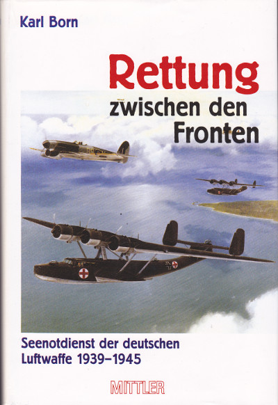 I ordered the book “Rettung zwischen den Fronten – Seenotdienst der deutschen Luftwaffe 1939-1945”. This book was written by Karl Born – The father of search and rescue at sea, and the aircraft that he used. The first one was the He-59-C 2, the one I am modelling here.
The book comes with some amazing close-up photos of this aircraft.
09/05/2015
Heinkel He-59
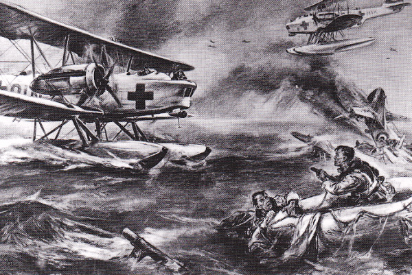 Just one picture from the awesome book that I discussed in the entry earlier.
08/02/2015
Heinkel He-59
05/04/2015
Heinkel He-59
15/09/2012
Levasseur PL-8
 The story about the Levasseur PL-8 “L’Oiseau Blanc” is almost too impossible to believe.
Charles Nungesser, known as French First World War aviation’s “ace of aces” and François Coli, his navigator, took off from Paris on May 8, 1927, in the hope of reaching New York. However, they vanished in their Levasseur PL-8 aircraft just 13 days before Lindbergh completed his landmark New York to Paris flight aboard the Spirit of St. Louis.
The mystery of their demise has remained intact for the past 80 years and observers at the time assumed they had gone down over the English Channel or off the coast of Ireland. Bernard Decré, a retired French pilot, now claims to have found US Coast Guard archival records suggesting the Frenchmen made it across the Atlantic. The document from August, 1927 records the sighting of a “pair of white wings” drifting in waters off Boston.
Mr Decré believes the pilots crashed in the vicinity of Saint-Pierre-et-Miquelon, the French islands between Newfoundland and Nova Scotia, after stormy weather forced them to abandon their plans for a direct flight. The document, he said, tallied with earlier eyewitness references to aircraft parts floating in the same area. He has pieced together accounts of more than a dozen Newfoundlanders who saw a plane flying over the southeast of the islands and from several French fishermen who heard an aircraft in the thick fog enveloping Saint-Pierre that day.
Mr Decré has not ruled out the possibility that the pilots were shot down by associates of Al Capone, as the French island were a prime destination for bootleggers during the Prohibition and Capone was a regular on Saint-Pierre.
The other possibility is that the plane was taken down by the US coastguard who mistook it for a smuggler’s craft. Parts of the archives had been curiously removed.
Mr Decré believes storms forced the pilots to abandon their plans for a direct Paris-to-New York flight. The most likely scenario, he said, was that they crashed into the sea after a failed landing in fog.
Specifications:
Crew: 2
Length: 9.75 m
Wingspan: 14.60 m
Height: 3.89 m
Max speed: 193 km/h
Range: 7000 km
16/09/2012
Levasseur PL-8
 The 3-Views I will be using are from the expedition crew that has started searching for l’Oiseau Blanc for the last 10 years. It is fairly detailed, and yet not. Together with photos of the original aircraft, it should be possible to piece a detailed model together.
16/09/2012
Levasseur PL-8
 Is it only me, or does the fuselage of this “Bird” look like a whale?
16/09/2012
Levasseur PL-8
 The original aircraft was made of plywood, so it scales really easily. The fuselage mostly consists of simple box-shaped plywood formers. The same goes for the wings, elevators and rudders. The only tricky bit is the engine cowl, which was made of metal.
03/02/2013
Levasseur PL-8
 The fuselage sides have now been cleaned up, a crutch has been added to simplify the construction, and the engine cowl has been lofted. There are still some cut-outs in the fuselage formers needed as well as beefing up of the longerons, and then I can move on to the engine and the engine mounting box. Incidentally, the engine mounting box will also be used to hold the lower wings.
10/02/2013
Levasseur PL-8
I have discovered that the fuel-tank was a cylindrical drum located horizontally between the firewall and the cockpit, resulting in the aircraft having a flat top there. The 3-view does not match that. I will have to fix it.
03/02/2013
Levasseur PL-8
I need to do the following:
18/08/2013
Levasseur PL-8
 I found this drawing of the aircraft. I LOVE IT! At the time of writing, I am preparing my workshop for the winter, so it could take a little time to get started on this aircraft, but it is really one of my favourites.
05/04/2015
Levasseur PL-8
13/11/2011
MiG-3
 The MiG-3 was one of the first aircraft I ever wanted to model. Unfortunately I did not have the skills back then. Time has now come to start modelling this amazing Russian fighter plane.
Specifications
Crew: One
Length: 8.25 m (27 ft 1 in)
Wingspan: 10.20 m (33 ft 5 in)
Height: 3.30 m (10 ft 9⅞ in)
Wing area: 17.44 m² (188 ft²)
Airfoil: Clark YH
Empty weight: 2,699 kg (5,965 lb)
Loaded weight: 3,355 kg
Powerplant: 1 × Mikulin AM-35A liquid-cooled V-12
Maximum speed: 640 km/h at 7,800 m
Maximum speed at sea level : 505 km/h
Combat range: 820 km
Service ceiling: 12,000 m
1 × 12.7 mm UBS machine gun
2 × 7.62 mm ShKAS machine guns.
2 × 100 kg (220 lb) bombs, 2 spray containers for chemicals, gas or flammable liquids or 6 × 82 mm RS-82 rockets
13/11/2011
MiG-3
 There are so many great 3-views available on the internet for the MiG-3. I have, however, found a great one in a Czech book, that I will be using.
13/11/2011
MiG-3
 The model is going to be to scale 1:5, or in other words:
Wing-span: 2.040 m
Length: 1.650 m
In other words, a pretty decent sized model.
I will be using the “For Russia” winter camouflage paint scheme as shown in the picture.
13/11/2011
MiG-3
 First thing is to import the 3-views into Alibre CAD and scale everything. I then normally make a “flat” 3D model, just to see how things look. Next, I will draw the fuselage formers and stick them onto this “3D crutch”.
05/04/2015
MiG-3
22/09/2012
Mitsubishi Ki-46 Dinah
 Although fighter and ground attack versions of the Dinah were developed, it was as a high-altitude photographic reconnaissance aircraft that the Ki-46 was most successful. Indeed, it was so successful that Germany tried to acquire manufacturing rights from Japan.
The Ki-46 first flew in November 1939 . The top-speed of 540 km/h was 60 km/h slower than required, but it was still faster than the latest Japanese fighters! New engines were attached during 1941, and the Dinah reached its required speed of 600 km/h. The Mark III Dinah which is the one I will be modelling here, had further improved engines, and a more stream-lined cockpit area, giving it a speed of 630 km/h.
The aircraft was first used over China, but the most successful missions were those flown over British Malaya before the Japanese invasion. Its high-altitude capabilities and long range meant that the Dinah could cover the entire Pacific theatre with almost no opposition.
The Dinah became vulnerable to fast-climbing Allied fighters at the end of the conflict, but still made many reconnaissance missions over the large American air-bases in the Mariana Islands at the end of the war.
Specifications:
Crew: 2 (pilot and observer)
Length: 11.00 m (36 ft 1 in)
Wingspan: 14.70 m (48 ft 2¾ in)
Height: 3.88 m (12 ft 8¾ in)
Empty weight: 3,263 kg (7,194 lb)
Loaded weight: 5,050 kg (11,133 lb)
Max. takeoff weight: 5,800 kg (12,787 lb)
Powerplant: 2 × Mitsubishi Ha-102 Army Type 1 14-cylinder radial engine at 1,080 hp
Maximum speed: 604 km/h (326 knots, 375 mph) at 5,800 m (19,000 ft)
Cruise speed: 400 km/h (217 knots, 249 mph)
Range: 2,474 km (1,337 nmi, 1,537 mi)
Service ceiling: 10,720 m (35,200 ft)
Climb to 8,000 m (26,250 ft): 17 min 58 sec
Guns: 1× rearward-firing 7.7 mm (.303 in) Type 89 machine gun
22/09/2012
Mitsubishi Ki-46 Dinah
 The 3-views I will be using come from the Japanese magazine “The Maru Mechanic”, November 1978. It is extremely detailed, and it should not be a huge problem drawing this set of plans.
22/09/2012
Mitsubishi Ki-46 Dinah
I have been to RAF Hendon in the UK, where they have the last surviving Dinah. I’d like to thank the lady guard from Zimbabwe for having time to chat with me, and for letting me cross the barriers and take some photos of this elegant aircraft.
In addition to the walk-around from RAF Hendon, I also bought the November 1978 issue of Maru Machanic which is dedicated to the Dinah.
So, all in all, I have enough documentation to get started.
23/09/2012
Mitsubishi Ki-46 Dinah
Oh, I forgot, the scale will be 1:5, giving the model a size of:
Wingspan: 2.94 m
Length: 2.20 m
Height: 0.776 m
22/09/2012
Mitsubishi Ki-46 Dinah
 I love the way the Japanese designed their fuselage formers. Simple and straight-forward. Why did the rest of the world have to make things so complicated? The fuselage of the Ki-46 Dinah had the same cross-section as the Tachikawa Ki-55, and the Mitsubishi Zero, i.e. two ellipses with different vertical radius, joined at the thrust-line. It just could not be simpler.
The 3-view from Japan was also extremely accurate.
This is the quickest I have ever made the fuselage formers – EVER! Doesn’t it just look so incredibly fast?
22/09/2012
Mitsubishi Ki-46 Dinah
 The fuselage does not have an engine. It’s basically an empty shell. I am holding it all together with a crutch. I am almost done drawing the stringers and “hollowing out” the formers. It’s coming together quickly.