Category Monospar S.T.25

Monospar S.T.25 – Introduction

Without finishing my other two R/C Scale Plans, I have begun collecting information about my next plane. The Monospar S.T. 25.  There is only one left – In Denmark of all places.

As the name implies, the wing in this plane has only one spar, and an ingenious way to keep it rigid, using bracing wires “spiralling” around the spar.

The S.T. 25 is the last in a series of almost identical planes, starting from the S.T. 4, then S.T. 10, 11, 12 and finally S.T. 25.

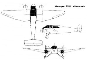
I was promised a decent 3-view of this plane by a guy in Denmark, but even without it, it is possible to piece a 3-view together, based on photos and 3-views of the other monospar models. They are that similar.

Monospar S.T.25 – Photo

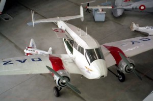
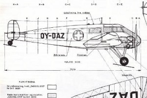
I now have sufficient information to start working on this plane. The guy never sent me that 3-view. I’m putting a decent 3-view together. Here is a photo to show what this plane looks like. Coming soon!

Monospar S.T.25 – Specifications

The Monospar S.T.25 has the following specs.

Wingspan: 26’4″
Length: 40’2″
Height: 7’10”
Maximum speed: 130 mph
Maximum altitude: 2.460 miles
Landing speed: 50 mph
Engine: 2 x Popjoy Niagara II (90 HP)

So far, all existing 3-views are total crap (possibly with the exception of the one from the guy who didn’t send it to me). Problems include wing profile and aileron shape.

Scale Size at 1:5:

Wingspan: 1605.3 mm
Length: 2448.6 mm
Height: 477.5 mm

Monospar S.T.25 – Rudder

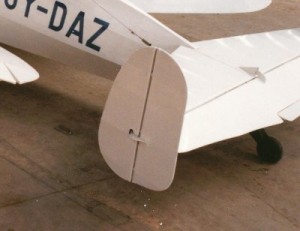
Since the 3-views are crap, I will combine the various 3-views and overlay them on the available photos to get the right shapes.  Also, since the Monospar was a UK aircraft, all measurement must have been in inch and we will round up/down to the nearest imperial units. i.e. 1/4″, 1/8″, etc.

I will start with the rudder.

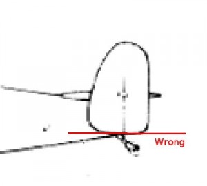
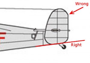
Comparing the three-views with the photo it’s clear that:

  1. The lower edge of the rudder is flush with the ground when the plane is on the ground.
  2. all curves are circles, with the exception of the top leading edge.

So, now we can draw the actual rudder.

This is going to be a pain of a project.

Monospar S.T.25 – Pain in the Ass!

This is gonna be my worst project ever. It will require a total re-draw of the 3-view. The problem is I have ZERO experience with 2D CAD drafting using ANY CAD program. All I know is that I hate AutoCAD. Simply can’t get my head wrapped around it. At this stage I’d rather draw it by hand. HELP!

Monospar S.T.25 – Walkaround available

I have been to the Danmarks Tekniske Museum in Helsingør. They have the sole surviving Monospar hanging in a couple of steel wires under the roof. Luckily they also had a ladder and a really helpful volunteer so I could get some photos of this gorgeous aircraft.

Monospar S.T.25 – 3-View Available

I have managed to locate a detailed 3-view for this aircraft. It is of really high quality, and made by taking measurements off of the actual aircraft. I can’t wait to get started on this fantastic little plane.

Actually it is not all that ‘little’. With a span of 12.3 m, and a scale of 1:5, it gives a good scale size.

Scale Dimensions

Wingspan: 2.46 m
Length:  1.58 m
Height:  0,50 m


Monospar S.T.25 – Fuselage Formers

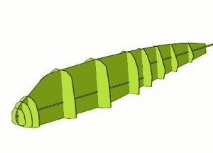
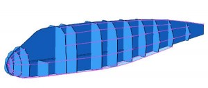
All the fuselage formers available in the 3-view have been done. The remaining will be lofted and added later.

Monospar S.T.25 – Cleaning up Formers

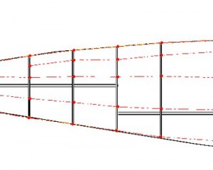
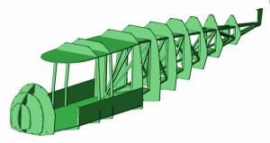
I now have to adjust the fuselage formers slightly, until they fit the top and side-views 100%. I do this by drawing in the longerons. Once drawn in, it immediately becomes obvious which formers needs correcting. These discrepancies on the 3-views are typically due to distortion during scanning or copying, as well as the problems with very thick pencil lines – It is not always possible to find the center of a line 100%. The picture here only shows the longerons on the side-view, but the top-view will also be used to correct the formers.

Monospar S.T.25 – Flat Configuration

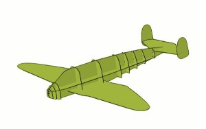
I have now completed the tedious job of cleaning up the fuselage formers. They now fit properly, and the longerons now follow a nice smooth curve, all the way from nose to tail. I have drawn the wings and empenage outlines, just to get an idea what the model will looks like.

Monospar S.T.25 – Lofting Remaining Formers

The remaining formers are then lofted. These are primarily around the cockpit area. Also, for strength, formers are inserted so that there is one approximately every 10 cm, except for locations where there is going to be a window or some other cutout.

Finally, everything is checked very very carefully, as there is no going back, if errors are discovered in the fuselage shape  at a later date.

Monospar S.T.25 – Fuselage Strength

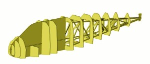
The original aircraft was constructed from metal tubing and canvas. In the model, to get enough strength, I have decided to use a square internal truss. The formers are only there to give the correct fuselage shape. This has the benefit of easy construction, whilst still allowing the exterior to look like the original aircraft. The much stronger internal truss will also be able to properly support the elevator and rudders. Both the longerons in the truss, and those used to get the external shape are spruce.


Monospar S.T.25 – Truss

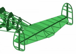
I have now completed the truss for the tail section, as well as made cut-outs in the rear formers. The truss has all the necessary strength and the formers are there, merely to give the fuselage the right shape. The airplane’s elevator will rest on the truss, and the tail wheel will be mounted on the rear end of it. The truss should be built the normal way, as two identical sides stacked on top of each other. It’s a light-weight solution, and rather clever, if I say so myself.

Monospar S.T.25 – Longeron strength.

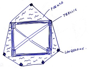
The main problem with the strength in the tail is that there are so few longerons. The problem of structural strength was solved by the internal truss. However, the covering is only going to be supported by the longerons, so they have to be plenty strong. There is no point in a strong aircraft, where a finger can bend the longerons and distort the fabric covering.

I did some experiments with bending sticks of spruce this afternoon. It is quite clear that the longerons must be at least 6 mm thich, to prevent any bending. Anything less than 6 mm was too weak, and anything over was difficult to shape. If 6 mm does not prove to be strong enough on the real aircraft, I will add some balsa supports from the truss to the longerons, to make them more rigid.

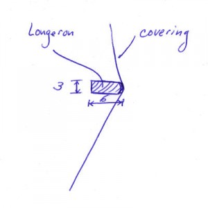
The actual aircraft uses 1/2″ pipes, which translates to approx. 2.5mm on the model. I have decided to round that up to 3 mm. The dimensions for a longeron will then be 3 x 6 mm and arranged as in the picture.


Monospar S.T.25 – Stuck Again

I’ve hit another snag. I do not have enough detail photos of the Monospar’s elevators. I have no idea what the hinges looks like. I also do not have a proper photo of the profile used for the elevator. I am most inclined to believe that the elevator is constructed similarly to that on the Tiger Moth – a contemporary aircraft. Both were using welded steel construction. If I were designing an aircraft like this, I would make the leading edge of the movable part of the elevator from a constant-diameter pipe. However, my photos of the Monospar show that the elevator was indeed using a (symmetrical) wing profile. I can’t reconcile the curved elevator with a constant thickness movable part. I also do not have a clear photo of the elevator hinges.

I will have to return to the museum in Helsingør to get some more detail photos. Too bad. In the meantime, I am going to work on another aircraft, or possibly the Monospar’s wings.


Monospar S.T.25 – Wing Crutch.

I have been studying the Ziroli Beechcraft C-45 model, and I will be using his wing and tail attachment method. Basically it is a standard crutch, with the exception that it uses a snap-fit design. The elevator will be using a crutch at the leading edge, but a set-screw at the back, similarly to the original. This is required, because the original has a gap under the elevator that I will have to simulate.

Next, I will be adding the outside stringers, then move on to the wing crutch, and the nose of the aircraft. When that is done, I will handle the tail section and finish the fuselage interior and the doors, windows and other hatches.

Monospar S.T.25 – Magazine

I have found a magazine on e-bay showing 3-views and the history of the monospar. It should be in the mail soon.
 

Monospar S.T.25 – Magazine II

Got one more magazine. Still not what I wanted.


Monospar S.T.25 – Museum Visit

I will be visiting the museum to take photos of the missing details on the 29th this month.

I need photos of wing hinges, elevator hinges, rudder hinges, wing profile.

The design of this aircraft will continue after I return.

Monospar S.T.25 – New material

I was at the museum yesterday, and finally got the information I was looking for – well, almost. The wing hinges are clear to me now, and I have some idea about the wing profile and the elevator. However, I had to deduce how the elevator was designed by examining the exterior look. Sometimes there is no choice, when the aircraft is suspended from the ceiling.


Monospar S.T.25 – Empenage

The empenage parts are now done. However, I still need to find a way to securely attach the rudders to the elevator. I will work on that next, as well as the push-rods, rudder horns, bellcranks etc.

Monospar S.T.25 – Cabin

I have started on the cabin area. It is kind of tough, since it has a large glass area, yet has to be strong. Here is what I have so far – a box.

Monospar S.T.25 – Related posts

Comments

  • Ed Clayman  says:

    The S.T.25 is well suited to electric…good because of its extremely small
    radial cowls. I have a plastic model made by Azur with decent detail and a
    fair amount of docs gathered online from a New Zealand museum, and ambulance
    version at your museum.

    Ed Clayman
    ScaleAero@gmail.com
    http://www.FliteMetal.com


Leave a reply