Category Fieseler Fi-167

Fieseler Fi-167 – Introduction

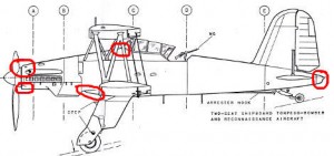
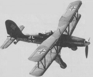
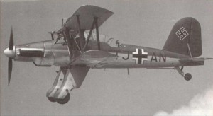
The Fieseler Fi-167 was a two seat single engine biplane designed for use on the Graf Zeppelin aircraft carrier as a torpedo bomber and reconnaissance aircraft.

It was the winner of a design competition between Fieseler and Arado. Like the famous Storch, the Fi-167 had amazing slow speed capabilities and was able to land almost vertical on a moving aircraft carrier.

Two prototypes were built, and 12 pre-production aircraft. There were very few modifications between the two. The aircraft exceeded all requirements by far, and had excellent handling capabilities and could carry about twice the required weapons payload.

When the construction of Graf Zeppelin was stopped in 1940, the aircraft production was halted, and the 12 aircraft in existence were entering service in Test Group 167 (“Erprobungsgruppe 167″).

After the Stuka took over as the major dive bomber, nine of the Fi-167s were sent to Holland at a naval squadron, until 1943 when they were sold to Romania. The 3 remaining aircraft were used at the German Aircraft Experimantal Institute (Deutsche Vesuchsanstalt fur Luftfahrt”). None exists today.

The specifications:

Length: 11.40 m (37 ft 4 in)
Wingspan: 13.50 m (44 ft 3 in)
Height: 4.80 m (15 ft 9 in)
Powerplant: 1? Daimler-Benz DB 601B
Maximum speed: 325 km/h (176 knots, 202 mph)
Cruise speed: 250 km/h (135 knots, 155 mph)
Range: 1,300 km (703 nmi, 808 mi)
Service ceiling: 8,200 m (26,900 ft)
Guns: 1 7.92 mm MG 17 machine guns, 1 MG-15 machine gun in rear cabin.
Bombs:
1 x 1000 kg (2,200 lb) bomb or
1 x 765 kg (1,685 lb) torpedo or
1 x 500 kg (1,100 lb) bomb plus 4 x 50 kg (110 lb) bombs

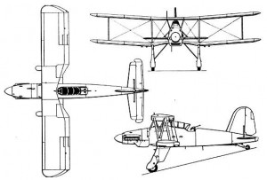
Fieseler Fi-167 – 3-View

I have collected all the information I could get – which is not much. However, I believe it is enough to get a decent model out of it. It might not be 100% scale, but as a first attempt, I think it will be pretty good.

I will design this using CAD, and then do the build. I will be using a mixture of (inadequate) 3-view drawings, the available photos, and a Czech plastic kit, and common sense during the design phase. I am a pretty fast builder, but really slow at CAD, so it might take a while before wood chips starts flying.

Fieseler Fi-167 – Information

I have been collecting photos and bought two books. One is the autobiography of Gerhard Fieseler and the other is an academic report on the Fi-167.

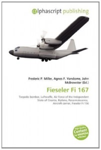
WARNING – AVOID THIS RIP-OFF PUBLISHER!

The “academic report” from Alphascript Publishing is a complete rip-off. First of all, it has the wrong aircraft on the cover, and the contents is two (2) pages from Wikipedia about the Fi-167 and the rest of this useless piece of shit publication is random aviation facts. The $60 + shipping I paid is a complete RIP-OFF!

Fieseler Fi-167 – Plastic model

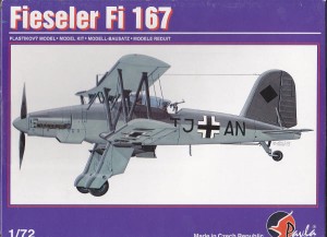
I have received the plastic model from Pavla Models in the Czech Republic.

The first thing I need to do is to verify that the 3-views I have are accurate, and that the plastic model I got is too.

Since the 3-views I have are less than stellar, I probably won’t be able to do any lofting of the fuselage formers based on them. Instead, I hope the plastic model corresponds well with the pictures of the actual aircraft, so I can take measurements off of that.

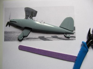
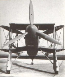
To see if the plastic model is to scale, I printed out the photo of the real aircraft, and placed the plastic parts on top of it.

It fits to a T (with the exception of the tail wheel). Very impressive work by the Czechs. It is quite clear that the plastic model is the way to go, compared to the 3-views. I’m one very happy camper.


Fieseler Fi-167 – Detailed 3-View

I have received a detailed 3-view from Deutsches Museum in Berlin. Interestingly enough, it was drawn by Bjorn Karlstrom – one of the most prolific aircraft artists ever. I have a lot of Swedish magazines dating back to the 1940’s and they are full of drawings by Karlstrom. Most of them, I suspect, he drew from photos, without having ever seen the actual aircraft.

The Fieseler Fi-167 drawings are up to the typical Karlstrom standard, with the exception of a couple of spots. In particular, he got the cowl shape wrong on the side-view. It just doesn’t look “shark-like”, but more like the cowl from a Piper Pawnee!

I will have to overlay the 3-view with the photos and correct this problem before I can continue.

I will obviously have to look through the 3-view in detail to see if anything else needs fixing. At first glance, it looks great, though.

Fieseler Fi-167 – Airfoil

I have not been able to identify the actual airfoil used based on the Karlstrom drawings, so I had to revert back to the available photographs.

The closest I could find was the Goettingen 676. This turned out to be the same airfoil used on the Fieseler F2-Tiger. Coincidence? I don’t think so.

Interestingly enough, this airfoil shape does not have a lot of camber, and the lift coefficient is quite average. The stall angle, however, is huge.

Compared to the extremely slow-flying Storch, I believe Fieseler chose the Goettingen 676 airfoil for this aircraft, to get a decent cruise-speed. However, with all the slats and flaps in operation, the Fi-167 lift coefficient could be increased by at least a factor 3 during take-off and landing.


Fieseler Fi-167 – Initial CAD work

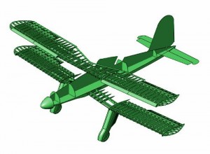
I have scanned the 3-View into the CAD program and am ready to trace the outline of the aircraft.

There are many ways to skin a cat, and I always draw my aircraft to the scale of the model, not to the scale of the real aircraft. I think it is easier – a 3mm balta sheet gets drawn with a thickness of 3mm. No conversion is required once the 3-Views have been imported and scaled to the size of the model. It also makes it easier to “plug in” models of servos and engines to see if they fit.

The 3-Views are almost always slightly off. They have been distorted by the photocopy process, humidity and other factors. They are hardly ever completely symmetrical, and the left and right side of the aircraft may not correspond 100%. The same with the top view – it may not correspond 100% with the side view, etc. etc. This is where common sense comes into the picture.

Odd measurements should probably be rounded to the nearest integer numbers, i.e. the width of the fuselage was measured as 24,119 cm (1.20595 m on the real airplane) and was rounded down to 24 (1.20m on the real airplane). The distances between wing ribs should probably be identical too. It is more likely that the guy who drew the 3-View was sloppy, than the engineers at the Gerhard Fieseler Werke spread out the wing ribs at random distances. It is quite tedious work, but once done, I have a 3-View with all the measurements I need.

Fieseler Fi-167 – High-lift devices

The Fieseler Fi-167 aircraft had a ridiculous amount of high-lift devices. It is said that Gerhard Fieseler during a demo sank the aircraft from 9800 ft to 100 ft, practically over the same spot while having full control over the plane. Ths is probably the aircraft with the most slats and flaps ever built. The Fi-167 had 2 automatic and independent slats on each wing – very exciting, but it will be hell to model. Not only were there a lot of high-lift devices, but they were also huge. A total of 10 percent of the chord is slats and 20 is flaps approximately.


Fieseler Fi-167 – Upper wings

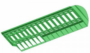
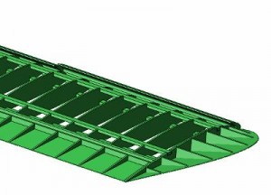
The upper wings are of the “candy-bar” design, i.e. they are not tapered towards the wing-tip.

Using the Goettingen airfoil, I have drawn the top wing in CAD.


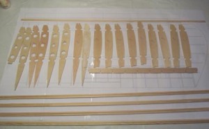
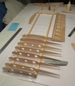
I then cut out the wing ribs. I did this with a scroll-saw for the ply wood parts, and with a scalpel for the balsa parts. If you do not have a scroll-saw, you can use a fret-saw, a hacksaw, or practically any other saw. cut 1 or 2 mm outside the line, and sand down to the line for the best results.


Finally, I  glued it all together using white wood glue. I prefer this glue for spruce, as it penetrates into the wood and gives a stronger joint than i.e.cyanoacrylate (superglue).


Fieseler Fi-167 – Wing tips

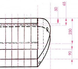
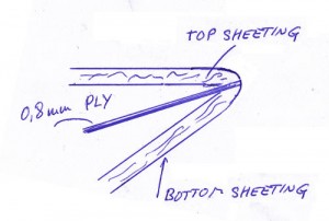
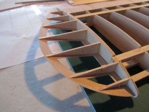
The wing-tips on this aircraft proved a bit of a headache. It is not the normal shape, but the top of the wing is flush all the way to the tip.

After a lot of head-scratching, here is what I came up with.

…and drawn in Alibre.

… and when cut from wood.


Fieseler Fi-167 – Flap hinges

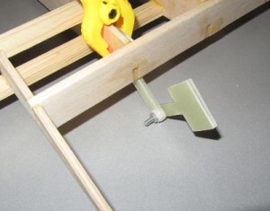
Since my order for wood still has not arrived, I decided to work on the flap hinges. I cut them from PCB material.

Here is the hinge dry-fitted to the top wing. I quickly realized that a single layer of PCB is not enough, and I will have to cut some more. The two hinge parts are joined with a nylon bushing and an M3 screw and lock-nut.


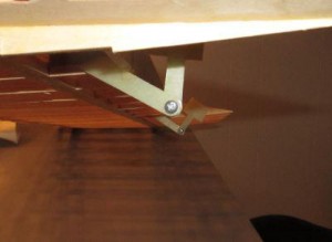
Here is the wing seen from the side. Yes I know the hinge-shape is slightly wrong. The vertical part should be more rounded, and the part to the left should be a bit fatter. I will clear that up in the CAD drawing and make a new set.


Fieseler Fi-167 – Flaps

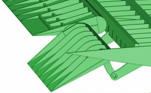
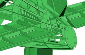
I spent all day drawing the flaps in CAD. I just couldn’t wrap my head around it.  The 3-view, and the panel lines on the plastic model, had me completely stumped. Since, I do not have a photo of the top side of the lower wing, I could not confirm it, and nothing seemed to match. I have literally drawn every type of aileron, flap and hinge combination in the book, including Friese types. The only 3-view showing the flaps correctly, is the ugly coloured one from Germany.

Anyway, I got there in the end.

Fieseler Fi-167 – Fuselage

I have been looking at the fuselage formers in the 3-view, trying to figure out how they were originally created. So far, I have figured out that the top of the fuselage, from the thrust-line and up, was, in essence, elliptical in shape. I have not yet figured out how the lower parts were created. Since I know that they were elliptical in shape, all the way from the prop to the tail light, it will be really easy to draw in the missing ones.


I also added a rough landing gear, and “glued” it all together. I am happy with the result, but a lot of work is still required. The biggest problem will be figuring out the lower part of the fuselage.

Fieseler Fi-167 – The word is out!

The word is getting out, that I am working on the Fieseler Fi-167. One of the leading UK plastic-modelling website now links to me. Together with the link from the Italian modelling forum, I should get more visitors, which is great.

Fieseler Fi-167 – Fuselage cleanup

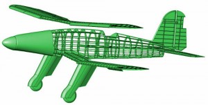
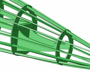
I have spent the entire day cleaning up the fuselage. I decided to use a crutch and stringers. There are 16 stringers all the way around the fuselage. They are simply there to prevent the fuselage from twisting while the sheeting is added.


Fieseler Fi-167 – Empenage

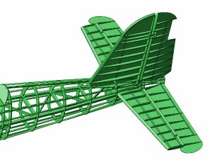
Yesterday I drew the tail. It consists of a crutch that the elevators can rest on. The idea is to build the crutch first, then glue in the lower longerons, then the sheeted elevator and then the upper longerons. The fuselage will be sheeted with balsa afterwards. Next step is to do the same with the rudder.


Fieseler Fi-167 – Engine mounting box

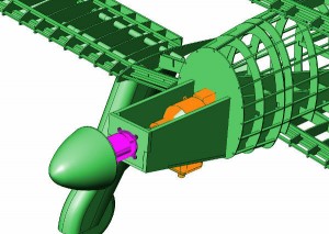
I have started on the engine mounting box. There are two engine options. 1) A Hacker A60L electric brushless motor, and 2) A ZDZ-40 petrol engine. The Fieseler Fi-167 has a very long and narrow cowl, and these were the only two engines I was was able to fit, without a huge hole in the side of the airplane. The ZDZ-40 moved back 20 cm will fit the engine cooling fins where the actual cooler was on the Fi-167.

The engine mounting box should be assembled first, so I have to figure out how to make the firewall and how to fix the crutch and the fuselage formers to the box.


Fieseler Fi-167 – Tail

I have fixed some strength issues in the tail. First of all, making room for the pushrods etc., proved a headache. It is getting really crowded back there.

Next I will be the strengthening up of the former where the tail-wheel is going to be attached.


Fieseler Fi-167 – Landing gear

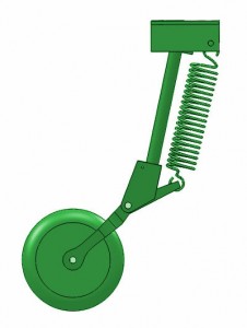
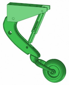
I have now done the landing gear. Despite being non-retractable, there is quite a bit of mechanics in there. I hope I will be able to machine the parts.


Fieseler Fi-167 – Tail wheel

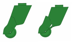
And the tail wheel assembly. This requires the machining of a shock absorber. I hope this goes well.


Fieseler Fi-167 – Related posts

Comments

  • sean yellow horse  says:

    I would like to try to produce the fi 167 I do mean the full size aircraft not a model or a childs toy yes I well aware that it will take a great deal of money but in the near future I will able to afford it I have an invention that will make this happen but I know without exact plans my idea will not fly no this is not a joke it can happen but I do need extensive help plans and pitorials and then I will have to find an original power plant it can be done !!

  • Eugénio  says:

    I just wanted to say i appreciate your work.
    Congratulations!

  • admin  says:

    Thank you. I just wish I had more time to work on it.

  • Mikael Vendel  says:

    Hi! I have read your detailed reports and commmend you for your good work! Are there any pix of the finished plane,and perhaps your impressions,experiences regarding flying the model? I am also glad you used the swedish illustrators drawings,since I had some of his on my walls when I was a young boy.
    Kind regards,
    Mikke Vendel
    Karlstad,Sweden

  • Ed Clayman  says:

    Jesper,

    Its been too long! In the mean time I have retired as has my building partner in our team
    scale projects. He moved to Kentucky where after buying the top of a mountain to erect a
    retirement home…he’s almost got the barn (code for shop) erected. His log cabin will be
    another 6 to 8 weeks of erection and finish out…deep winter in Kentucky.

    How much more of the 167 CAD is complete? I am most anxious to mill and cut the parts for
    this. What did the final w/s end up being after adjusting the CAD along the development?

    Looking forward to hearing from you. Earlier today I made new inquiries to find the large
    Fred Spring technical drawings. Were you fortunate to have located a set?

    Ed Clayman
    FliteMetal.com
    ScaleAero@gmail.com

  • Ed Clayman  says:

    Jester

    Have you given up on the CAD Fi-167? Would have been nice to have
    received a reply to my post above. Since posting it I have made an
    additional effort relative to acquiring Fred Spring’s Fi-167 tech
    drawings. Bob Holman here in the States has the drawings except of
    course the Fi-167.

    Looking forward to hearing from you at ScaleAero@gmail.com

  • Kasmar  says:

    A very interesting aircraft and indeed a very challenging project, my respect! Will you ever publish a comprehensive report on this model?

  • Ed Clayman  says:

    Has any further development of the Fi-167 occurred? I am interested in CAD files of what has been developed to CNC cut parts and print components.

  • Sascha Reinhardt  says:

    Great work and tech Solutions on this plane! There is not much to find about the plane and the Details. Especially the Flaps and slats. Is it possible to get some Infos and files?

    Please don’t give up this Project as it is a very rare and interesting one.


Leave a reply