 Requirements
Sometimes we, as engineers, get jobs with conflicting requirements. This week was one of those weeks. We needed a high-voltage, high frequency amplifier that could drive purely resistive, but also highly inductive and capacitive loads.
- Frequency: 200kHz square wave
- Output Voltage AC: 1.2Vp
- Output Voltage DC: 0 – 50 V
- Load: < 25 Ohm, highly inductive
Problem:
There are many audio amplifiers that can handle this load, but in our design the output must swing around a DC voltage of up to 50V. This is a tough one. On top of that, a 200kHz square wave has very high 3rd and 5th harmonics, so we need an amplifier with a bandwidth of at least 1 MHz.
High frequency + high power + high voltage = Trouble
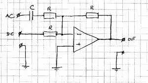
Now, my first instinct was to look at various commercially available parts. There were a couple of high-power (read > 100V supply voltage) amplifiers with a decent bandwidth. The most promising was the LM3886. My initial plan was to configure it in a standard mixer configuration, with two inputs, one for DC and one for AC, as shown below:

The problem with this circuit is that it is inverting. We need a large negative voltage on the DC input, to get a large positive DC voltage on the amplifier’s output. However, this can be easily fixed with some inverters on the inputs. So, I used the LM3886 from National Semiconductors to build this circuit. THREE MAJOR PROBLEMS:
- Amplifier get’s amazingly hot, amazingly fast. It’s always driving 50V onto it’s output. This is not healthy for a class AB type amplifier. Quiescent power consumption is very low, but operational is just as high as a class-A type amplifier.
- It couldn’t handle a 1.2V swing on top of the 50V output. The slew-rate just wasn’t high enough.
- Configuration needs a ton of external op-amps to flip the negative input voltages into positives.
Solution:
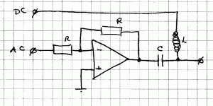
For those of you old enough to build stuff using discrete components, the solution is very simple. Use a small AC amplifier and superimpose the DC voltage on the amplifier’s OUTPUT. Yes, you heard me… OUTPUT! Superimposing a low-frequency signal (i.e. DC) and a high-frequency signal (i.e. out 200kHz signal) is very easily done. An inductor blocks AC and a capacitor blocks DC. We now have:

A couple of quick calculations later gets us a C of around 100uF, and an L of 10mH. Easy-Piecy.
As the amplifier now only handles the AC part, we now no longer require 50V output swing on the output amplifer. With a required swing of 1.2Vp on the output, we can set the supply voltages to, say, +/- 5V and we set the gain of the amplifier to one.
A low gain helps us tremendously, because amplifier gain rolls off with frequency. In fact, the term “gain-bandwidth product” has been used. An amplifier with a gain-bandwidth product of say 100,000, has a gain of 100,000 with a 1 Hz signal, but a bandwidth of 1 with a 100,000 Hz signal. In other words gain multiplied by the frequency is a fixed value.
So, now all we need to find is an amplifier that can drive a 25 Ohm load, resistive as well as not, with a gain-bandwidth product of 1MHz.
The choice fell on the TDA2030A for a few reasons.
- It’s specs are according to our requirements.
- It’s cheap and easily available.
- It already has protection diodes to prevent spikes feeding back into the amplifier when switching off the big coil.
- Mono amplifier.
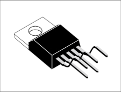
- PentaWatt package can dissipate around 2W without external heatsink.
- Allows a non-inverting configurations, saving all those nasty negative voltage on it’s inputs.
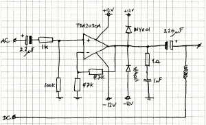
So we end up with the final schematic:

Click image to zoom in.
The 4.7k resistors in the feedback path sets the gain to one. The two 1N4001 diodes protects the amplifier when switching off the DC input voltage. The other components have been left as in the original schematic, except for the capacitors that have been scaled to work up to 1MHz, instead of the original 20kHz bandwidth.
And that was that… EASY!


