Category Projects
Project – Antenna rotor #1 – Design
Project – GPIB bus interface #1 – Introduction
In episode one I discuss the GPIB protocol and how data and commands are transferred on the bus.
Project – GPIB bus interface #2 – Schematic
In this installment, I discuss the design choices and how I arrived at the final schematic for the GPIB bus interface.
Project – GPIB bus interface #3 – PCB layout
In the 3rd episode, I discuss the PCB layout.
Project – Antenna rotor #1 – Design
It’s not difficult – Idea
CP/M computer
SCHEMATICS COMING SOON
Introduction
Although from the mid 1970’s and with limited memory, CP/M machines are still very useable today. Some of the available software programs are marvels of engineering. There were C, COMAL, Fortran and Pascal compilers available, as well as wordprocessors, text editors, spreadsheets and games.
The first CP/M machines consisted of a CPU, RAM, a boot ROM and one or two serial ports. The CP/M operating-system was designed for for use with 8″ floppy disks. These disks were large and could hold 180kBytes each. Later the smaller 5 1/4″ disks were adopted.
The CP/M machines did not initially come with a monitor and keyboard. Instead a teletype terminal and a line printer was used for input and output, respectively. Later on VT100 terminals were used, and around 1980 the typical CP/M machine came with the VT100 terminal built in. However, for software compatibility the built-in VT100 terminal and the main computer unit were still, two separate units, but on a single PCB.
In this post, I will design and built a CP/M machine using standard components. A VT100 terminal is also in the works, but it will be a plug-in board. For mass-storage, I will be using SD Cards.
A lot of software has been written for CP/M, and I imagine my ‘clone’ is ideal for places where a VDU, keyboard and floating point algorithms are required. I have seen CP/M machines used for telescope control, tracking stars, for example. After all, a CP/M machine is SO much easier to program than a microcontroller.
Hardware Overview
The machine will be using a 4 MHz Z80 CPU, an 8-bit ROM, a static RAM and some control logic. The supply of Z80 SIOs is unreliable, so I will use tWO 16550UARTS for the serial portS. I initially wanted to use Compact Flash instead of the floppy drives, but I couldn’t find the cf connectorS locally, so I changed to SD Cards. I will use a couple of TTL gates to interface these.
I have a small wall-mounted PVC enclosure in mind, and if there is room on the PCB, I plan to include an 8-bit input/8-bit output port too.
CPU
The CPU is a standard 4MHz Z80 CPU. These days static RAM is really cheap, so the memory refresh pins of the CPU associated with dynamic RAM are unused. I will use a single interrupt for the serial ports.
The CPU needS a single quad-OR gate to combine the RD, WR, IORQ and MEMRQ signals into something useful.
There is no other support logic required to get this CPU running with the exception of a clock signal.
Clock and Reset Logic
The 16550 serial port chip normally requires an 8 MHz clock. However, I have decided to use a 4 MHz clock to save logic. Obviously all serial-port speeds will have to be re-programmed. i.e. 19200 Baud at 8 MHz will only be 9600 Baud at 4 MHz.
Two resets switches, or a single multi-position switch, is used on most CP/M machines. These provide: 1) A hard reset that will re-boot the computer, and 2) a Soft reset which simply restarts the CP/M system using the program already loaded into RAM.
Memory
Under CP/M, all programs run from RAM. During power-up, a boot-ROM in the lower part of the memory is used to load the operating system from the floppy disk into the higher part of RAM. When done, the boot-loader will then jump to an address in RAM and perform an I/O write to switch out the boot ROM and switch in the lower RAM.
The memory on my CP/M computer consists of a Boot-ROM and a Static RAM. A flip-flop that is reset during a hard reset will switch in the Boot-ROM. An IO Write will set the flip-flop and switch out the ROM. Apart from that, there is nothing special about the memory circuit
I wanted to do some memory bank switching, but the CP/M operating system uses both the lower and the upper memory areas, and swapping memory banks in the middle of the memory map is really not a good solution, so I have decided against it.
Serial I/O
Only one serial port chips is required. As I use my own VT100 terminal hardware, I can connect that directly to the Z80 bus. A MAX232 is used to convert TTL to +/-12V levels.
SD Cards
SD cards are basically using the SPI data format. The Z80 doesn’t have any I/O ports, so I have added these. For people used to working with microcontrollers like the Microchip PIC, this is a real waste of TTL gates, but in the late 1970’s this was how it was done.
PCB Layout
The CP/M computer consists of two PCBs. I have done this to fit it into the PVC enclosure that I had available. An alternative layout would be on a single 10×16 cm Euro-Card. If there is any interest in the eurocard form-factor, let me know.
Software
Two pieces of software is required to get CP/M to run. The first is the Boot-ROM. The second is the BIOS. The function of the Boot-ROM is explained above. The BIOS is a bit of code that translates CP/M function calls like “load” and “save” into hardware specific I/O operations.
Boot-ROM
In order to understand the Boot-ROM, we need to look at the CP/M file-system and how data is arranged on the floppy drive.
BIOS
The standard BIOS code that comes with CP/M needs to be modified to support our hardware. In particular, we need to handle the SD Cards. On these cards, data is shifted out serially, and one block of data is 512 bytes each. On the original 8″ Floppy drives, data was transmitted byte-wise, and a blocks-size of 128 Bytes were used.
Finally, we need to handle the serial-ports, so that programs like PIP can run successfully.
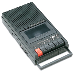
Cassette tape recorder
 Introduction
The home-computer of the early 1980’s was a low-cost device. It had to be. Nobody knew if it was a fad or was going to take off. Many were bought by parents for their kids. A retail price of several 100’s of dollars would put many people off.
To keep costs low, practically all computer manufacturers made use of products that people already had in their home. The TV was used for the display, and a small tape recorder was used for data storage.
The TV is still around, but the low-cost tape recorder is not.
Functional Description
In this build thread I am going to design a solid-state tape recorder. I won’t be using any fancy features. The solid-state tape recorder will work in exactly the same way the original did. There will be a counter, a play, a record, a stop, a fast-forward and a rewind button. You will actually have to sit and wait for the tape to rewind.
You can’t stick your finger through one of the holes in this solid-state audio cassette and spin it around to manually to rewind it, but hey… that’s progress for you.
Initial Calculations
My first idea was to simply same the programs as audio on a flash or EEPROM memory device. However, a quick calculation shows that a play-time of 45 mins would require:
45 [min] x 60 [sec/min] x 8000 [samples/sec] = 20 MBytes
Way too much memory for a simulated cassette tape costing less that $2 in 1990.
We clearly have to save our programs as memory images instead of audio tracks. So we get to the final design:
- Standard cassette-tape interface.
- Data saved from the computer will be demodulated by our tape recorder and stored as a memory image.
- Memory images are modulated before being sent to the computer.
- A USB interface will be included for uploading of memory images from a PC.
Design
Project – CNC Router #1 – Introduction
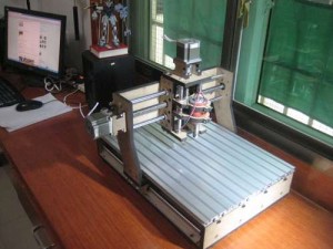 This build-thread is a bit different to the other threads here, in that I am building a CNC router, and not an airplane model.
A CNC router is a computer controlled router that is able to cut out fuselage formers, wing ribs and other model parts from foam, balsa, plywood and even aluminium, directly from a PC. It will save me a ton of time, and ensure that all the parts come out identical.
The picture on the right shows a similar design to what I have in mind, only smaller.
Early on, I settled on a maximum parts size of 120 x 70 x 30 cm. In hindsight this is probably a little on the small side. Since I later had the idea of cutting entire cowl-plugs from foam with the CNC, I should have gone for 60 cm in the Z axis (upwards). Anyway, all is not lost, as I can “slice” the cowls in the software, cut out the slices individually, and then glue the slices back together again after they have been cut out. Not ideal, but it will work.
The largest size parts the CNC router can cut was not the only choice I had to make. Before starting the design, speed, accuracy, motor type, control electronics, cost and availability were all things that needed considering. I’ll quickly run through the various options.
- Speed is an obvious factor in a production environment, but for my hobby use, any speed will be faster than cutting parts out by hand, so I gave it a low priority.
- Accuracy is important, however, because of the small size parts I plan to make. I decided on an accuracy around 0.1 mm as “good enough”. Accuracy is determined by the motor type, and most importantly the drive-train. To avoid slop and backlash, I decided on a design with ballscrews and linear guideways. They are a quite a bit more expensive than the lowest cost ball-bearing and threaded metal rods, but they remove practically all slop and backlash.
- There are basically two types of motors: Servo and steppers. Servo motors are by far the best choice, in that the computer knows where the cutter is at all times. Stepper motors, on the other hand, are moved blindly, and the PC basically hopes that the hardware moved the cutter to the position specified. If the stepper motors get stuck or misses a step, the piece being cut is ruined. The trick is to use stepper motors a lot more powerful than actually necessary. I went that route, as the servo option was too expensive for my budget, and a lot more complicated to set up.
- Control electronics for stepper motors are a lot cheaper than the servo controllers, mostly because stepper motors are being used in practically every computer printer out there, driving the cost all the way down.
- Availability. Before I found a great little shop in the Netherlands, my only choice was e-bay, so I bought both the electronics and the mechanical parts from companies in China.
The quality of my parts are decidedly Chinese, i.e. varying from bad to worse. The linear rails are great though, and I wish I could say the same about the ballscrews. While the ballscrews themselves are really nice, the nylon covers at both end are slightly out of spec, and prevent the ballscrews from moving freely. I hope the nylon will get worn a bit when in use. Also, the ball-bearings I got felt like there was sand in them. I got a handful new ones from a roller-skate shop. The Chinese shaft couplers looks acceptable. One other major problem, besides the nylon on the ballscrews, is the lock-nuts. They need to be machined to the proper size, at some point, before they can be used.
I bought four big-ass stepper motors, and a stepper motor control board and power supply. Everything ready for use by the Mach3 software. I heard a lot of bad things about the Chinese controller boards, but they look pretty decent, and besides, I am an electronics engineer by trade, so I think I can handle those.
All I now need to do is to get the mechanical design done. Since I am only going to cut balsa and plywood, my CNC cutter will be made from MDF board. MDF board is easy to cut and fairly strong. I don’t even have to do such a neat job out of it. When the CNC is up and running, I can use it to cut parts for itself.
Project – CNC Router #2 – Stepper Motors
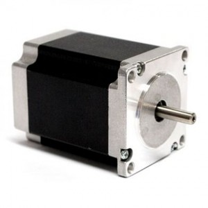 I decided on the NEMA 23 standard stepper motors. They seem a good compromise between power and weight.Besides, I am not cutting steel with these.
First of all, they are 27V motors, having a holding torque of about 0.9Nm. I know 5V stepper motors are available these days, but from experience I find them weaker and slower than the high-voltage equivalents. I will be running them from a 24V switch-mode power supply.
Secondly, the NEMA23 stepper motors turn 1.8 degrees per step. My ballscrews rotate 5 mm per revolution, giving:
5 [mm/rev] * 360 [degr/rev] / 1.8 [degr/step] = 0.025 [mm/step].
Pretty decent accuracy, if you ask me.
A quick look in Google reveals that the motor will be able to do about: 5 rev/sec without sacrificing torque, giving a linear speed of 25 [mm/s]. Not exactly stellar, but I’d rather have the accuracy than speed. So, there we have it:
Specifications:
Accuracy: 0.025 mm
Speed: 25 mm/s
Torque: 0.9 Nm (without ballscrew “gearing”)
Project – CNC Router #3 – Design
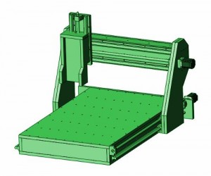 My design is based on MDF board. MDF board is made by pressing a wood-chips and glue mixture into plates. They cheap, easy to machine and adequately strong.
I have chosen to go for a movable gantry, instead of a movable table. This saves a lot of real-estate, but the gantry has to be quite sturdy. Apart from that, this CNC router is of a standard design.
The footprint of the machine is 120 x 80 cm, and an active table size of 100 x 70 cm. the Z-axis is able to move 20 cm up and down.
Fender Telecaster – Introduction
I found this cool video on youtube showing Phil X demonstrating a 1966 Fender Telecaster, and I simply MUST make one of those. It sounds way cool.
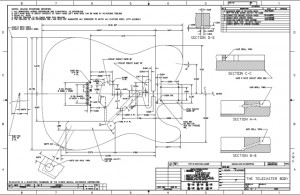
Fender Telecaster – Plans
Fender Telecaster – Electronics
Pick-ups will be:
DIMARZIO DP175-BK
and
SEYMOUR DUNCAN SSTHR-1B BLK Humbucker pickup in single coil.
Tone control potentiometer: 500 kOhm, volume control potentiometer: 200 kOhm and the roll-off capacitor 330 nF.
Greenland Kayak – Introduction
Coming soon…


 05/05/2016

Leave a reply